AIDE: Week Twelve
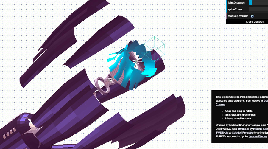
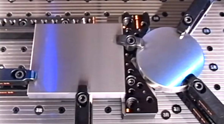
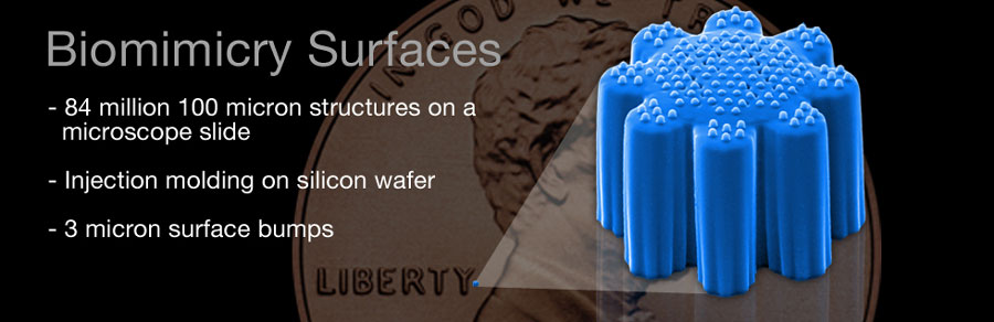
Micro Engineering
Building micro products and micro tools
Sublimation Printing
Affordable product customisation

FEA
Finite Element Analysis is commonly used in aerospace, automotive and architectural engineering with 2d or 3d computer simulation models to solve complex shapes.
Initial work towards creating the analysis was done, separately, by Alexander Hrennikoff and Richard Courant during 1941-1942. Although the two used different approaches, they shared one essential idea: mesh discretization of a continuous domain into a set of discrete sub-domains, referred to as elements.
Starting in 1947, at Imperial College, Olgierd Zienkiewicz used these approaches to form what would later be called the Finite Element Method (FEM), building the pioneering mathematical formalism of the method. Today the Finite Element Method is used in any and all aspects of mathematics and physics; from visualization of how a car deforms in an asymmetrical crash to solving complex elasticity and structural analysis problems in civil and aeronautical engineering.
Key Benefits of Using FEA in Virtual Product Development
Reduce product development time and cost by reducing design iterations
Reduce product development time and cost by reducing the number of prototypes constructed
Reduce the amount of physical product testing, it is still very important to conduct some physical tests
Reduce time to market
Increase product quality through better understanding of how the product stands up to it's intended use
The earlier FEA is introduced into the product life cycle the better
Use FEA to drive product design
The Principal has over twenty years of varied FEA experience doing stress, thermal, and dynamic analyses
Solidworks FEA
FEA Tutorial Bending of a Cantilever Beam in SolidWorks.
SolidWorks takes a look at this classic cantilever beam fixed at one end with a sheer load or moment applied to the other end. Using one interface, you can review both the model and the deflection results to the analytical solution.
Join Esfand Kouhi from Intercad (http://www.intercad.com.au) as he explores SolidWorks FEA Simulation. This webcast will cover Simulation Seats in SolidWorks, Finite Element Definition, SolidWorks Simulation Interface, SolidWorks Simulation Options, SolidWorks Simulation pre-processing and SolidWorks Simulation post-processing.
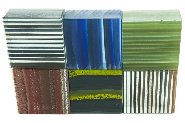
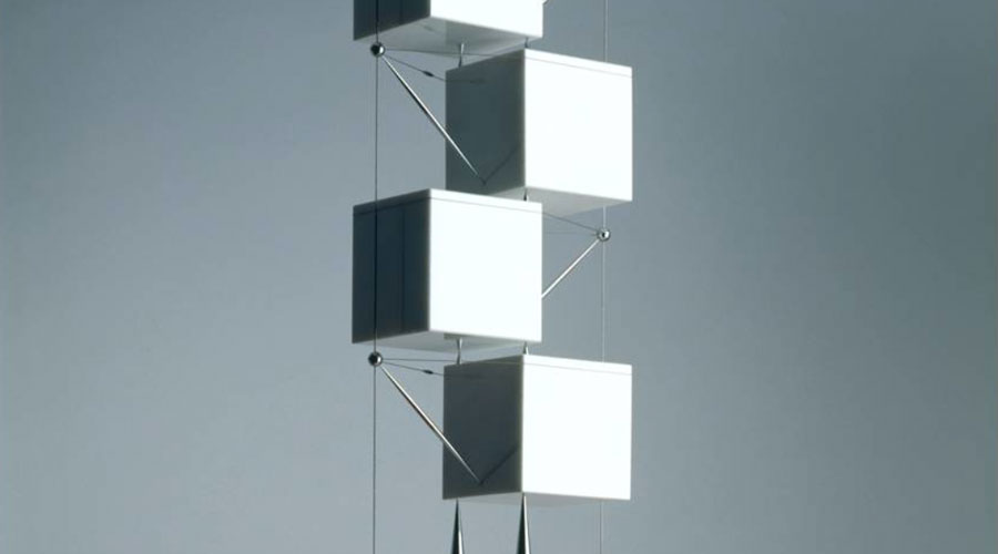
The Rise of the Creative Glass
Architectural glass surfaces.
'The Architectural Glass Surfaces are patterned glass materials. It is made using a combination of post-industrial and reclaimed glass in a two to one ratio. The material is manufactured by Interstyle by fusing the glass with ceramic stains under intense heat to form flat slabs of glass to create a gentle ‘ribbon’ look.' Materia.nl
Download Presentation pdf
Assignment 3: Product Design
Propose a new building brick to replace a Boral hollow concrete brick to function in a complimentary manner, by way of design and material specification.
Hollow concrete brick assignment by studiobutcher on Sketchfab
Engineered Building Block - Range Extension
Engineer a complimentary and sympathetic alternative engineered block design to function alongside the range of Boral Series 150 concrete hollow building blocks.
Within the dimensional parameters of 390mm x 190mm x 140mm consider
Materials and components suited to Australian conditions.
Assemblies and processes targeting future building technologies.
Production materials and processes suited to medium volumes with an eye to development for higher volumes.
Fire risk building sites
Proposal requirements
At least two distinct materials and manufacturing processes in your design.
Structural chassis.
Components for passive and/or active lighting, air flow and retrofit.
Assessment criteria
30% of overall grade
Creativity of your design in regards to use of materials, processes and originality.
Technical understanding and application in regards to how the different components are designed and the level of detail shown.
Overall quality of the documentation of the design.
Note: there is no price point restriction on your design. It can be either a low end or a high end application or both.
Deliverables
Submission is a landscape PDF document (or website page) that includes the following:
A ¾ view of the product – hero shot
An exploded view of the product with part numbers
A cross section of the product identifying how the internal components are positioned and secured by your housings.
A bill of materials (BoM) corresponding to the exploded view that includes material type, manufacturing processes and surface treatment if applicable.
One page written overview of the design
Post your document to the Wiki (located in Week 14 folder on Blackboard) at 9am, Friday,
October 31stNovember 7th (revised to avoid a clash with design studio submissions.)
Surface Profiles
Read the surface profiles section of textbook.
Continue development of your brick proposal.
Consider:
The current hollow brick properties manage thermal requirements already. We don't need to redesign the brick in this exercise to address pure thermal capacity. Rather, we want to produce a version which compliments that brick.
Brick production is clearly a volume production exercise. To build one house would be considered small/medium volume, and multiple houses would be high volume. In considering production processes for this assignment, your design can be targeted at building at least one house.
The number of bricks required to build a small domestic residence drives the economics of the project.
- Let's say I'm building a simple house with a floor area of 100m2. I'm using 390mm x 140mm x 190mm (high) hollow concrete bricks, so for two walls measuring 20m x 2.5m the area works out to be 50m2. So I'll say I need 3,870 bricks. Of these, I'd like 20% to have light and air permeability, which equates to 774 of these permeable bricks.
-
Boral provide a brick quantity calculator
The production process impacts project viability, for both off-site and on-site scenarios.
Presentation
Download this week's presentation here.
Surface Profiles
Common surface treatments can be divided into two major categories:
Treatments that cover the surface
- Organic (eg. Paints, cements. laminates, powders, etc)
- Inorganic (eg. Plating, dipping, thermal sprays, fusings, etc)
Treatments that alter the surface
- Hardenings (eg. Flame, induction, laser, etc)
- High Energy Treatments (eg. Laser & electron beam)
- Thin & Heavy Diffusion Treatments (eg. Case hardening)
- Special Treatments (eg. Magnetic and sonic)
Across these two categories the common processes include:
Printing
- Screen printing
- Pad printing
- Cubic printing
- Hot stamping
- In-mold decoration
Plating
- Vapor metalizing
- Electro-plating
- Electro-Less plating
- Anodizing
Polishing
- Mechanical polishing
- Electro-polishing
- Chemical polishing
Coating
- Solvent based painting
- Water based painting
- Electro painting
- Powder coating
- Enameling
Miscellaneous
Other various profiles